
How to Measure a Hydraulic Cylinder for Replacement
Quick Answer: To measure a hydraulic cylinder for replacement, record its bore diameter (if available), rod diameter, stroke, retracted and extended mounting lengths, mounting types, port specifications, and operating pressure. Measure from consistent reference points and document all dimensions with units. Compare the measurements with the original manufacturer’s specifications and the machine’s operating requirements before selecting a standard, tie-rod, welded, or custom replacement.
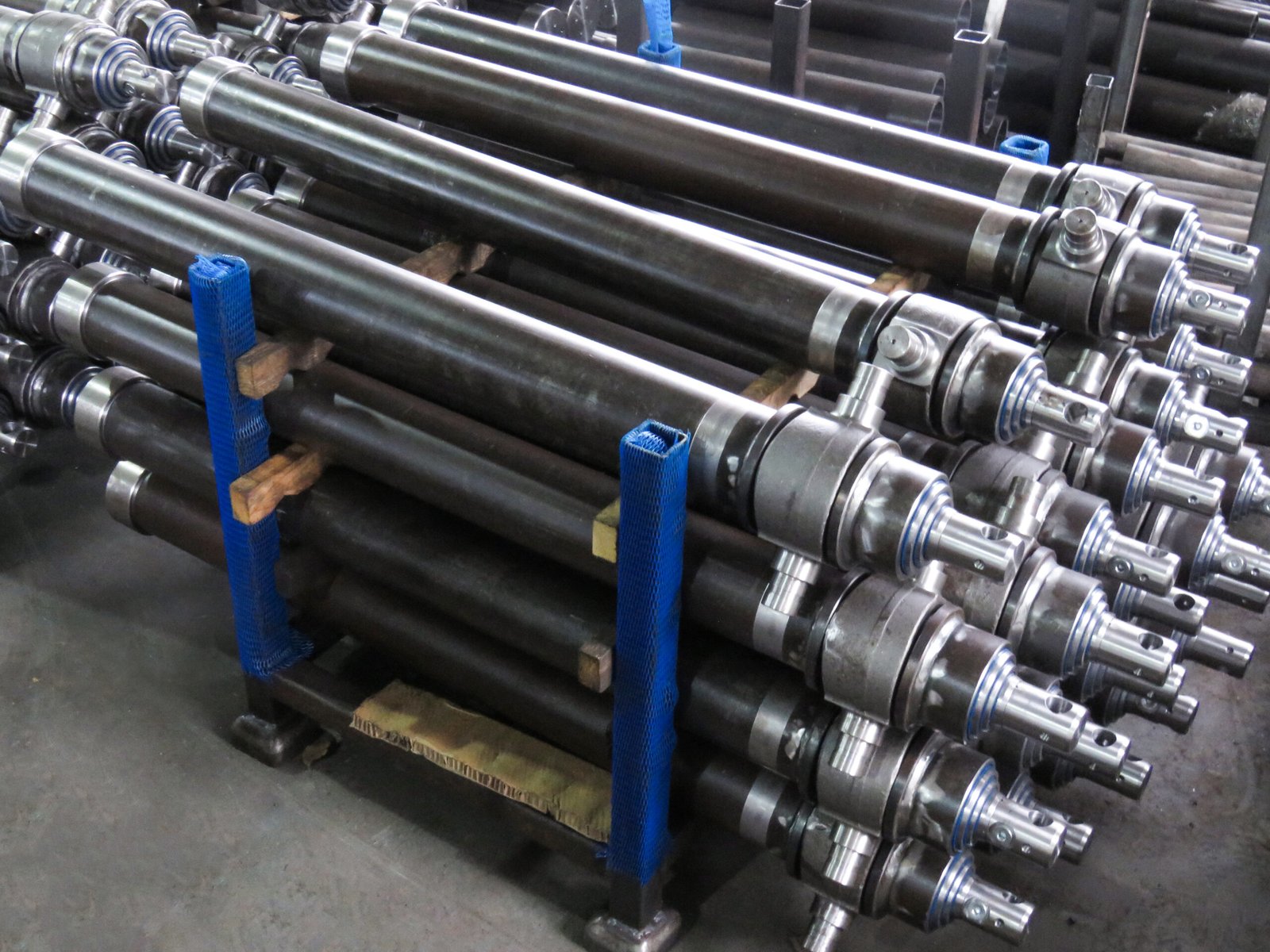
Safety First
Before you measure anything:
-
Depressurize the hydraulic system. Release all pressure before disconnecting lines or removing the cylinder.
-
Support the load. Use stands, blocks, or a mechanical lock — never rely on the hydraulic system to hold a load.
-
Wear PPE. Safety glasses and gloves protect against residual pressure, hot oil, and sharp edges.
-
Clean the area. Dirt and grit can enter open ports and damage the new cylinder.
Important: Never loosen a hydraulic fitting to check for pressure. Follow the equipment manufacturer’s lockout and depressurization procedure before disconnecting hydraulic lines or removing the cylinder. Do not operate or extend a cylinder under an unsupported load. If the cylinder cannot be measured safely in place, have qualified service personnel perform the inspection.
Tools You Will Need
| Tool | Purpose |
|---|---|
| Tape measure or steel rule | Stroke, retracted length, extended length |
| Calipers | Rod diameter, accessible dimensions |
| Micrometer (optional) | Precise rod measurement |
| Protractor or angle gauge | Mounting angle |
| Thread pitch gauge | Thread identification |
| Camera or smartphone | Photograph nameplate, mounting ends, ports, and overall structure |
| Manufacturer’s drawing or service manual | Verify dimension references and thread specifications |
| Marker and paper / worksheet | Record every dimension |
| Flashlight | Inspect accessible ports, pins, and visible surfaces |
Measurement Checklist
Before you start, confirm you have all of these:
- Bore diameter (if directly measured or confirmed from the manufacturer’s specifications)
- Barrel outside diameter (record separately if the bore is not accessible)
- Rod diameter
- Stroke length
- Retracted mounting length
- Extended mounting length
- Mounting type at both ends
- Pin diameter, pin-hole diameter, and pin-center distance
- Port thread type, size, position, and orientation
- Rated working pressure and system relief-valve setting, if available
- Cylinder type and model/part number
- Equipment make, model, and application
- Measurement units (inches or millimeters)
Step-by-Step Measurement
Step 1 — Identify the Cylinder Type
Before measuring, identify the cylinder’s construction and design. Common configurations include tie-rod cylinders, welded-body cylinders, telescopic cylinders, and other standard or application-specific designs. “Custom” describes a cylinder built to specified requirements rather than a separate construction type.
Identifying the construction helps determine which dimensions, mounting details, and manufacturer specifications are needed for replacement.
Step 2 — Determine Bore Diameter
The bore is the inside diameter of the cylinder barrel.
Important: The bore diameter is the inside diameter of the cylinder barrel, not its outside diameter. If the cylinder is assembled, the bore usually cannot be measured directly without disassembly. Do not estimate the bore by subtracting an assumed wall thickness from the barrel’s outside diameter.
For replacement identification, record the barrel outside diameter separately, along with rod diameter, stroke, mounting dimensions, and any model or part number. Provide these details, clear photos, and the equipment information to the manufacturer. These measurements may help identify the original bore, but the bore should be confirmed from the manufacturer’s drawing, part number, or direct measurement whenever possible.
Step 3 — Measure Rod Diameter
Use a caliper or micrometer to measure the exposed rod diameter at accessible, undamaged locations. Where practical, take measurements at more than one position and in more than one direction to identify visible wear, scoring, or out-of-round conditions.
Record the nominal or confirmed rod diameter separately from any worn or damaged measurements. Rod diameter affects seal dimensions, effective hydraulic area, and resistance to buckling under compressive loads.
Note: Common rod diameters vary by cylinder series and manufacturer. Confirm the actual specification rather than selecting a replacement based on a typical size list. Examples only: 1″, 1.25″, 1.5″, 1.75″, 2″.
Step 4 — Determine Stroke Length
Stroke is the distance the rod travels from fully retracted to fully extended.
Method A — Measure the actual travel
If the cylinder can be safely operated through its full stroke, measure the movement of a fixed reference point on the piston rod from the fully retracted position to the fully extended position.
Only measure actual travel when the equipment manufacturer’s operating procedure permits it and the load is safely supported. Do not force the cylinder to its end positions or bypass mechanical stops, load-holding valves, or safety interlocks. If full travel cannot be measured safely, use the original manufacturer’s specifications or have qualified personnel verify the stroke.
Method B — Compare mounting lengths
Measure the corresponding mounting dimensions at both positions. For a conventional single-rod cylinder with matching reference points, stroke is the difference between the extended and retracted lengths.
Do not assume that the exposed rod length equals the cylinder’s rated stroke. Check the manufacturer’s drawing or specifications whenever possible.
Step 5 — Measure Retracted Length
Measure the retracted length between the manufacturer’s specified mounting reference points with the cylinder fully retracted.
-
Clevis or eye mounts: Measure from pin center to pin center.
-
Flange mounts: Record the mounting face, bolt-hole pattern, hole diameter, bolt spacing, and the manufacturer’s defined length reference.
-
Trunnion mounts: Record the trunnion diameter, centerline location, spacing, and the distance to the rod-end mounting reference.
If the original drawing is available, use its stated dimension references. Do not assume that overall length is measured from the same points across different cylinder manufacturers.
Always use the same reference points when measuring retracted and extended lengths.
Step 6 — Measure Extended Length
With the cylinder fully extended under the manufacturer’s approved operating procedure and with the load safely supported, measure between the same mounting reference points used for the retracted-length measurement.
For a conventional single-rod cylinder, when both dimensions use identical reference points and the manufacturer’s dimension definitions, the difference between extended and retracted mounting lengths should correspond to the stroke.
Check: Extended mounting length − Retracted mounting length = Stroke, provided all three dimensions use the same reference convention.
If the measurements do not agree, check the reference points, end fittings, measurement units, and manufacturer’s drawing. Do not assume the formula applies directly to telescopic cylinders or to dimensions taken from different mounting references.
Step 7 — Identify Mounting Type
| Mounting Type | What to Record |
|---|---|
| Clevis / Eye | Pin-hole diameter, inside width, pin-center reference |
| Tang | Hole diameter, tang thickness, width, hole-center location |
| Flange | Bolt-hole pattern, bolt spacing, mounting face |
| Trunnion | Pin diameter, centerline location, spacing |
| Cross Tube | Tube outside diameter, inside diameter, width, centerline |
| Other / Custom | Photos, dimensions, orientation, original drawing |
Record mounting type at both ends — the rod end and the cap end may differ. Also record pin-hole diameter, pin-center distance, mounting orientation and angular alignment where applicable.
Related: Hydraulic Cylinder Mounting Types — see our guide to clevis, trunnion, flange, and other mounting configurations.
Step 8 — Measure Port Size and Position
Record the hydraulic port’s thread standard, nominal size, location, orientation, and connection type.
Common port standards include NPT, SAE straight-thread O-ring ports, BSPP, BSPT, and metric threads. Do not identify the thread standard from outside diameter alone. Use a suitable thread pitch gauge, thread identification tool, original drawing, or manufacturer’s specifications to confirm the connection.
Record the following for each port:
-
Thread standard and nominal size, if confirmed
-
Port location on the cylinder (side, top, end, or other position)
-
Distance from the manufacturer’s reference surface
-
Port orientation relative to the mounting features
-
Port connection and sealing method, where known
The replacement must have compatible ports and sufficient clearance for the hydraulic fittings and hoses. Matching port position alone does not confirm thread or sealing compatibility.
Step 9 — Record Operating Pressure
Record the cylinder’s rated working pressure and, where available, the hydraulic system’s relief-valve setting. Check the equipment manual, original cylinder nameplate, or manufacturer’s technical drawing.
Operating pressure is a key factor in verifying the cylinder’s pressure rating, force capacity, structural design, seals, and connection specifications. Do not assume that a replacement is suitable simply because its dimensions match.
If the operating pressure is unknown, have the equipment manufacturer or a qualified hydraulic professional verify the required rating before selecting a replacement.
Important: The system relief-valve setting and the cylinder’s rated working pressure are related but are not interchangeable specifications. Confirm both where possible.
How to Measure a Hydraulic Cylinder for Replacement
Once you have all dimensions, compare them to available standard sizes:
| Measurement | Why It Matters |
|---|---|
| Bore | Affects effective area, force, and bore seal dimensions |
| Rod | Affects rod seal dimensions, effective area, and buckling resistance |
| Stroke | Determines travel distance |
| Retracted length | Determines fitment in the machine |
| Extended length | Confirms stroke and mounting geometry |
| Mounting | Determines how it attaches |
| Ports | Determines hose connection |
| Pressure | Used to verify the pressure rating, structural design, seals, and connections |
Dimensional similarity alone does not confirm interchangeability. Verify the cylinder’s pressure rating, mounting geometry, load conditions, hydraulic connections, and application requirements before installation. A manufacturer may be able to identify a compatible standard alternative even when some external dimensions differ, provided the design and installation requirements are fully verified.
Find the Right Hydraulic Cylinder Replacement
Your measurements can help identify the right cylinder type for your replacement project.
| What You Need to Match | Toleng Product Category |
|---|---|
| A cylinder matching an available catalog series and its specifications | Standard Hydraulic Cylinders |
| A tie-rod cylinder with compatible dimensions and mounting specifications | Tie Rod Hydraulic Cylinders |
| A welded-body cylinder with compatible construction and mounting geometry | Welded Hydraulic Cylinders |
| Non-standard dimensions, mounting configurations, or application requirements | Custom Hydraulic Cylinders |
The product category is a starting point for identifying a replacement. Confirm the exact series, dimensions, pressure rating, mounting configuration, and application requirements before ordering.
Standard Hydraulic Cylinder
For applications matching available catalog dimensions and specifications.
View Product →
Tie Rod Hydraulic Cylinder
For tie-rod designs with compatible dimensional and mounting specifications.
View Product →
Welded Hydraulic Cylinder
For welded construction and compatible mounting configurations.
View Product →
Custom Hydraulic Cylinder
For non-standard dimensions, mounting configurations, or application requirements.
Request a Quote →
Related: Telescopic hydraulic cylinders use multiple nested stages to provide a long extension relative to their retracted length. If you are replacing a telescopic cylinder, record the overall retracted and extended lengths, mounting dimensions, port specifications, stage count (if known), and original model or part number. Do not disassemble or measure internal stages unless the manufacturer’s service procedure permits it.
See our [Telescopic Hydraulic Cylinders] guide or product category for application-specific information.
Common Measurement Mistakes
| Mistake | Consequence |
|---|---|
| Estimating bore from barrel outside diameter | Wrong cylinder size |
| Measuring rod at a worn spot | Wrong seal selection |
| Measuring extended and retracted lengths from different reference points | Incorrect stroke or mounting-length calculation |
| Forgetting to measure retracted length | Cylinder will not fit |
| Ignoring port thread type, position, or sealing method | Hoses or fittings will not connect |
| Assuming mounting is standard | Bolt pattern will not match |
| Assuming matching dimensions guarantee compatibility | Incorrect pressure rating, mounting fit, or hydraulic connection |
| Not verifying the cylinder’s rated pressure and system requirements | Undersized cylinder or premature failure |
| Measuring with cylinder under load | Inaccurate dimensions, safety risk |
| Mixing inch and mm measurements | Wrong dimensions, quoting errors |
Measurement Worksheet
Copy this worksheet and complete as many fields as possible. Use the same units throughout and identify the reference points used for length measurements.
HYDRAULIC CYLINDER MEASUREMENT WORKSHEET

Equipment Information

Equipment Make / Model: ______________________
Application: __________________________________
Cylinder Model / Part Number: __________________
Quantity Required: _____________________________
Measurement Units: [ ] Inches  [ ] Millimeters

Cylinder Dimensions

Bore Diameter (if confirmed): __________________
Barrel Outside Diameter: _______________________
Rod Diameter: __________________________________
Stroke Length: __________________________________
Retracted Mounting Length: _____________________
Extended Mounting Length: ______________________
Length Reference Points: _______________________

Mounting Information

Rod-End Mounting Type: _________________________
Cap-End Mounting Type: _________________________
Pin-Hole Diameter: _____________________________
Pin Center Distance: ___________________________
Mounting Width / Bolt Pattern: _________________
Mounting Orientation: __________________________

Hydraulic Connections

Port Thread Standard / Size: ___________________
Port Position and Orientation: _________________
Port Distance from Reference Surface: __________
Rated Working Pressure: ________________________
System Relief-Valve Setting (if known): _________

Supporting Information

Original Drawing / Part Number: _________________
Photos Attached: [ ] Yes  [ ] No

Additional Notes:
______________________________________________
______________________________________________

Send the completed worksheet, available photos, and original
drawings to Toleng for a technical review.
Standard vs. Custom Hydraulic Cylinder
| Factor | Standard Cylinder | Custom Cylinder |
|---|---|---|
| Dimensions | Matches an available catalog specification | Designed to approved project dimensions |
| Lead Time | Depends on stock and availability | Depends on engineering, materials, and production |
| Cost | Depends on model and quantity | Depends on specifications and quantity |
| Fitment | Requires dimensional and application verification | Designed around specified installation requirements and verified before production |
| Mounting | Available standard configurations | Custom mounting configurations may be available |
Choose a standard cylinder when the required dimensions, pressure rating, mounting, and application specifications match an available product.
Consider a custom cylinder when the required dimensions, mounting configuration, or performance specifications are not covered by an appropriate standard series.
Explore Custom Hydraulic Cylinders →
Need a Replacement Hydraulic Cylinder?
Send Toleng your cylinder measurements, mounting details, equipment information, and available photos or drawings.
Our engineering team can review the specifications and help identify a suitable standard, tie-rod, welded, or custom cylinder for your application.
Send Your Measurements →
Please include the original part number, rated pressure, and equipment model whenever available. Final compatibility should be verified against the approved technical specifications before ordering.
FAQ
How do I measure bore diameter if the cylinder is assembled?
In most cases, the bore cannot be measured directly without disassembly. Record the barrel outside diameter, rod diameter, stroke, mounting dimensions, and any model or part number, then provide these details and photos to the manufacturer. These measurements may help identify the original bore, but the bore should be confirmed from the manufacturer’s drawing, part number, or direct measurement whenever possible.
What if my measurements do not match a standard size?
If your measurements do not match a standard cylinder, a custom replacement may be required. A hydraulic cylinder manufacturer can review your dimensions, mounting configuration, pressure requirements, load conditions, and application to determine whether a standard alternative or a custom design is appropriate.
Can I measure a hydraulic cylinder while it is still on the machine?
Yes, some external dimensions can be measured while the cylinder remains installed, provided the equipment is secured and the manufacturer’s safety procedures are followed. Do not disconnect hydraulic lines or operate the cylinder under an unsupported load. Bore and internal dimensions generally require additional inspection or disassembly by qualified personnel.
What is the most important measurement?
There is no single measurement that confirms replacement compatibility. Retracted mounting length and mounting type are important for fitment, but bore, rod diameter, stroke, pressure rating, port specifications, and application requirements must also be verified.
How do I know if I need a tie rod or welded cylinder?
Look at the construction. Tie rod cylinders have visible rods running the length of the barrel. Welded cylinders have a smooth barrel with welded end caps. Structural appearance only helps with initial identification — final selection should be based on the original model, drawings, and installation dimensions.
Do I need to measure pressure?
Yes. Record the original cylinder’s rated working pressure and the system’s relief-valve setting, if available. These specifications help verify pressure compatibility, structural design, seals, and connections. Do not select a replacement based on dimensions alone.
Resources
-
How Does a Hydraulic Cylinder Work?
-
Hydraulic Cylinder Parts
-
Hydraulic Cylinder Troubleshooting

