
Master hydraulic cylinder pressure measurement. Learn the differences between absolute, gauge, and vacuum pressure, and how to select the right sensor to prevent cavitation and system failure.
1. Introduction: The Role of Pressure in Hydraulic Systems
In the world of fluid power, pressure is more than just a number; it is the “heartbeat” of the system. For a hydraulic cylinder, accurate pressure measurement is critical for:
- Force Control: Ensuring the cylinder exerts the exact tonnage required.
- Position Estimation: Calculating rod movement based on differential pressure.
- Safety & Protection: Preventing catastrophic failure due to over-pressurization.
However, many engineers struggle with choosing the correct pressure reference. Should you use an absolute or a gauge sensor? What happens if the system pulls a vacuum? This guide breaks down the physics and provides a foolproof selection framework.
2. Understanding the Three Types of Pressure
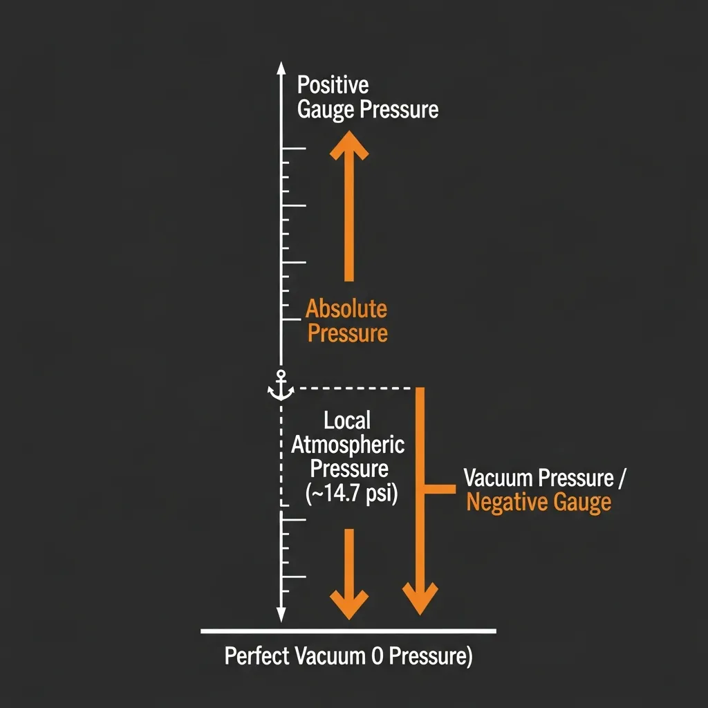
To select the right sensor, you must first understand what “zero” represents in your measurement.
| Pressure Type | Reference Point | Common Formula | Practical Example |
|---|---|---|---|
| Absolute Pressure (Pabs) | Perfect Vacuum (0 PSI) | Pabs=Pgauge+Patm | Barometers, Altimeters |
| Gauge Pressure (Pgauge) | Local Atmospheric Pressure | Pgauge=Pabs−Patm | Tire Pressure Gauges |
| Vacuum Pressure (Pvac) | Below Atmospheric Pressure | Pvac=Patm−Pabs | Suction Cups, Intake Manifolds |
SEO Pro Tip: Most hydraulic applications use Gauge Pressure because the work is performed against the surrounding atmosphere. However, Absolute Pressure is vital for high-altitude operations or precision closed-loop controls.
3. Unique Pressure Demands of Hydraulic Cylinders
Hydraulic cylinders operate under harsh conditions that differ from standard pneumatic or liquid piping.
Typical Operating Conditions
- Cap/Rod End: High positive gauge pressure (typically 70 to 350 bar).
- Return Line Backpressure: Low positive gauge pressure (approaching 0 bar).
- Suction/Makeup Lines: Potential for brief vacuum periods (negative gauge pressure), which can lead to cavitation.
Common Selection Pitfalls
- Using Absolute Sensors for Standard Work: This adds unnecessary cost and complexity as the reading will fluctuate with weather and altitude.
- Ignoring Negative Pressure: Using a standard gauge sensor on a line that experiences suction can lead to “clamped” signals or sensor fatigue.
- Ignoring Altitude: If a mobile crane travels from sea level to the mountains, a gauge sensor’s “zero” remains the same relative to the environment, but the absolute force changes.
4. 5-Step Pressure Sensor Selection Guide for Hydraulic Cylinders
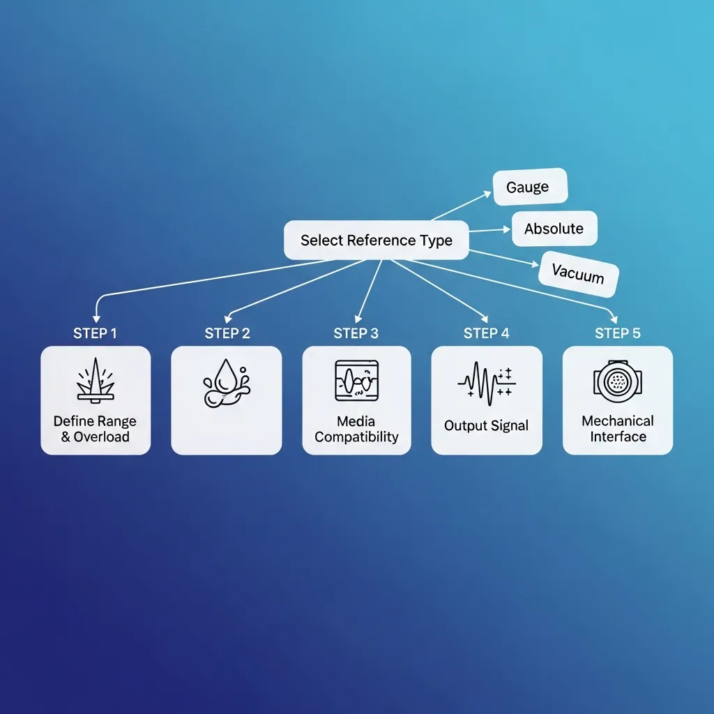
Step 1: Define Measurement Range & Overload
The rule of thumb is to select a sensor with a range 1.5x to 2x your maximum working pressure. Hydraulic systems are notorious for “pressure spikes” (water hammer). Ensure the sensor has high burst pressure ratings.
Step 2: Select Pressure Reference Type
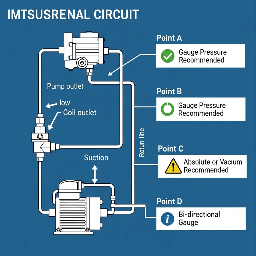
| Location in Circuit | Recommended Type | Why? |
|---|---|---|
| Pump Outlet / Cylinder Chambers | Gauge Pressure | Direct reflection of load pressure; most cost-effective. |
| Pump Suction / Makeup Circuit | Absolute or Vacuum | Detects cavitation or “air intake” issues. |
| Precision Servo Systems | Absolute | Eliminates atmospheric interference for high-accuracy loops. |
Step 3: Media Compatibility & Protection
Hydraulic fluids (mineral oil, water-glycol, or Skydrol) require specific wetted materials.
- Material: 316L Stainless Steel is standard.
- Ingress Protection: Look for IP67 or IP69K for mobile machinery exposed to rain or high-pressure washdowns.
Step 4: Output Signal & Accuracy
- Analog: 4–20 mA (best for long cables/interference) or 0–10 V.
- Digital: CANopen or IO-Link (best for Industry 4.0 and remote diagnostics).
- Accuracy: ±0.5% FS is standard; ±0.25% FS is preferred for precision control.
Step 5: Mechanical Interface
Standard hydraulic ports include G1/4 (BSPP), 1/4 NPT, or M14×1.5. For viscous fluids, consider a flush diaphragm to prevent clogging.
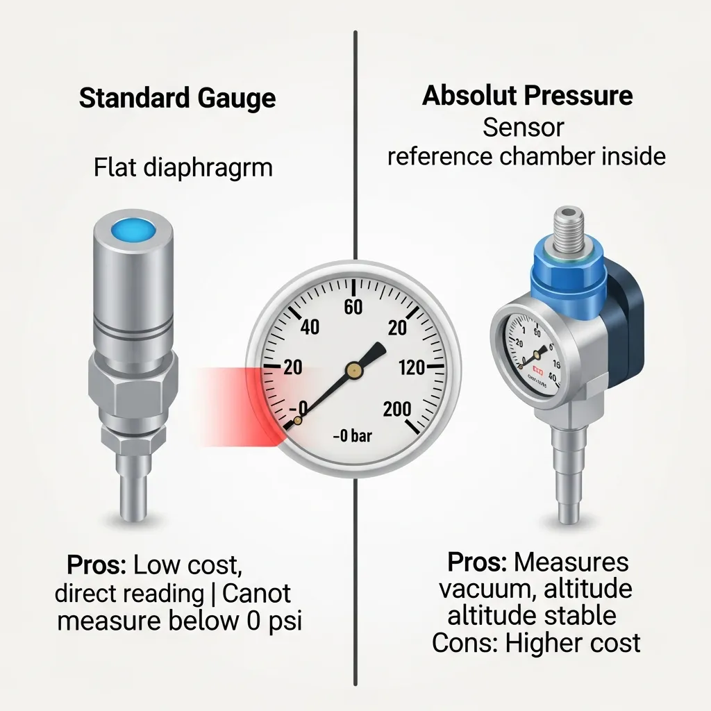
5. Standard Gauge vs. Absolute/Vacuum Sensors
| Feature | Standard Gauge Sensor | Absolute/Vacuum Sensor |
|---|---|---|
| Measure below 1 atm | No (Signal clamps at 0) | Yes |
| Altitude Sensitive | No (measures relative) | Yes (measures actual) |
| Relative Cost | Lower | Medium to High |
| Typical Use | 90% of Hydraulic Cylinders | Closed-loop pumps, Vacuum suction |
Key Warning: If your return line or rod end might experience momentary negative pressure (e.g., during rapid differential movement), use a bi-directional gauge sensor (e.g., -1 to +10 bar).
6. Real-World Selection Example
Requirement: A hydraulic cylinder operating at 250 bar. During rapid retraction, the cap end may briefly drop to -0.3 bar. The environment is outdoors with high vibration.
The Solution:
- Type: Bi-directional Gauge Sensor (Range: -1 to 300 bar).
- Output: 4–20 mA.
- Housing: Stainless Steel, IP67.
- Connector: M12 (for vibration resistance).
7. Expert Troubleshooting: Avoiding Common Mistakes
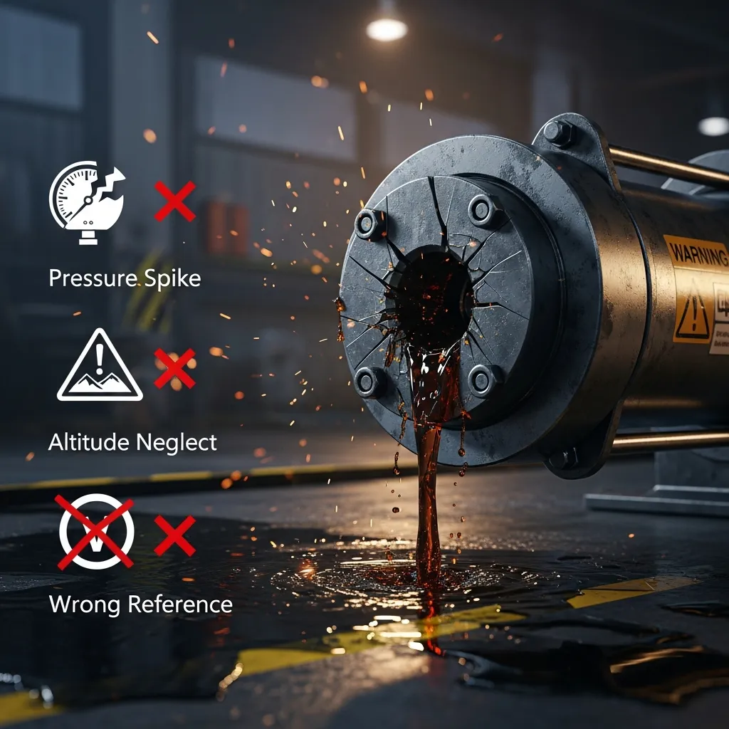
- The “Zero Shift” Error: If you use an absolute sensor but calibrate your PLC as if it were gauge, your readings will be off by approximately 1 bar (the atmospheric constant).
- Neglecting Damping: Use a pressure snubber or a capillary tube if the sensor is located near a pump to avoid damage from high-frequency ripples.
- The Altitude Trap: Mobile equipment designed at sea level using absolute sensors may fail to reach pressure setpoints when moved to high-altitude regions.
8. Conclusion & Final Checklist
Before purchasing your next hydraulic pressure sensor, run through this quick checklist:
- Does the range include a safety factor for pressure spikes?
- Is there a risk of vacuum/negative pressure in this circuit?
- Is the sensor output compatible with my PLC (4-20mA vs 0-10V)?
- Does the thread type match the cylinder port?
- Is the ingress protection (IP rating) sufficient for the environment?
By understanding the nuances of Absolute, Gauge, and Vacuum pressure, you ensure higher system reliability and more precise machine control.

